INTRODUCTION
Before
the production of any product, the second stage after Designing is Prototyping (making
a prototype). Prototyping is a process in which the design ideas are
implemented into tangible forms from paper to digital. Before production
prototype is used in various testing to prove the product is working. In
history this work is done by skilled craftsman i.e., manually but now-a-days
this work is done by 3D printing i.e., Rapid Prototyping (RP) – layer-by-layer
material deposition.
Timeline
of the Technology used
of the Technology used
|
Year of inception |
Technology |
|
1770 |
Mechanization |
|
1946 |
First |
|
1952 |
First |
|
1960 |
First |
|
1961 |
First |
|
1963 |
First interactive graphics system(early version of Computer |
|
1988 |
First |
BASIC
PRINCIPLE
PRINCIPLE
In contrast to subtractive or shaping
processes such as lathing, milling, grinding, or coining, RP belongs to the
generative (or additive) production processes. Material removal or plastic
deformation are used to shape the object. The first step in any commercial RP
process is to identify the target audience. Deposition of layers contoured in a
two-dimensional (x-y) plane fabricates the part. Single layers are piled on top
of each other to create the third dimension (z), but not as a continuous
z-coordinate. As a result, the prototypes are very accurate in the x-y plane
but stair-step in the z-direction. Model looks original when deposited with
very fine layers, i.e. reduced z-stepping. The development of mathematical
layer information and the generation of a physical layer model are the two
essential process steps in RP. The picture depicts a typical process chain for
various RP systems.
FIGURE 1
Figure 1 shows how the process begins with 3D
modelling of the product and ends with the STL file being created by
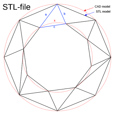
tessellating the geometric 3D model. Various surfaces of a CAD model are
piecewise approximated by a succession of triangles (figure 2), and the
coordinates of the vertices of the triangles, as well as their surface normals,
are reported. Figure 2 shows how facet deviation or chordal error determines
the number and size of triangles. These STL files are inspected for flaws such
as flip triangles, missing facets, overlapping facets, dangling edges or faces,
and are corrected if they are discovered to be defective. Various slicing
softwares accept defect-free STL files as input. Because part building time,
surface quality, the number of support structures, and cost are all influenced
at this step, the choice of part deposition direction is the most critical
element. The tessellated model is sliced and the resulting data in standard
data formats such as SLC (stereolithography contour) or CLI (common layer
interface) is stored once the part deposition orientation and slice thickness
have been determined. This data is used to proceed to step 2, which is the
creation of a physical model. Laser-scanning pathways (in processes like
Stereolithography, Selective Laser Sintering, and so on) or material deposition
paths are generated by the software that runs RP systems (in processes like
Fused Deposition Modeling). This phase varies depending on the technique and
the underlying deposition principle used in the RP machine. The information
gathered here is utilised to layer-by-layer deposit the part on the RP system
platform. Figure 3 depicts the generalised data flow in RP.
FIGURE 2
The post-processing task is the last stage in
the process chain. Because some manual activities are required at this stage, a
skilled operator is required. Excess elements attached to the part or support
structures are removed during cleaning. For a better surface quality or
aesthetic look, the model’s surface is sometimes sanded, polished, or painted.
After that, the prototype is tested or confirmed, and any proposed engineering
improvements are made during the solid modelling stage.
Generalized illustration of data flow
in RP
RAPID
PROTOTYPING PROCESS
PROTOTYPING PROCESS
There are some RP processes like –
·
Stereolithography
(SL)
·
Selective
Laser Sintering (SLS)
·
Laminated
Object Manufacturing (LOM)
·
Fused
Deposition Modeling (FDM)
Stereolithography
(SL)
(SL)
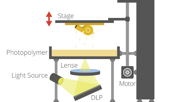
A
crucial element in this method is photosensitive liquid resin that solidifies
when exposed to UV light. Because of the absorption and scattering of the beam,
the reaction occurs only near the surface, forming voxels of solid polymeric
resin. A build platform (substrate) is mounted in a resin vat, and a UV
Helium-Cadmium or Argon ion laser is used in an SL machine. The first layer is
laser scanned, and the platform is then lowered to one slice thickness and left
for a short period (dip-delay) to allow the liquid polymer to settle to a level
and even surface and prevent bubble formation.
After
that, the new slice is scanned. The below figure is a schematic diagram of a
typical Stereolithography apparatus. As the blade traverses the vat in new SL
systems, it deposits resin on the part. This results in a smoother surface and
less time spent recoating. It also reduces trapped volumes that can occur when excessive
polymerization occurs at the ends of the slices, resulting in the formation of
an island of liquid resin with a thickness greater than the slice thickness.
The part is taken from the vat once it is completely placed, and the excess
resin is drained. Due of the high viscosity of liquid resin, it may take a long
period. After removing support structures, the green section is post-cured in a
UV oven.
Stereolithography (SL)
Because the green layer is unstable and weak,
overhangs or cantilever walls require support systems. If the overhangs, etc.,
surpass a specific size or angle, i.e., build orientation, they are supported.
The main purposes of these structures are to support projecting sections and to
bring down other parts that curl up owing to shrinking. These support structures
are created during data processing, and as a result, data expands rapidly,
especially with STL files, as cuboid-shaped support elements require at least
twelve triangles. It’s tough to remove a solid support later, and it may damage
the model.
Selective
Laser Sintering (SLS)
Laser Sintering (SLS)
Fine
polymeric powder (20 to 100 micrometre diameter) such as polystyrene,
polycarbonate, or polyamide is placed on the substrate using a roller in this
method. In order to reduce thermal distortion and allow fusing to the previous
layer, the temperature of the entire bed is raised slightly below its melting
point by infrared heating before initiating CO2 laser scanning for sintering of
a slice. The laser is tuned in such a way that it only affects the grains that
come into direct contact with the beam. After a slice has been laser scanned
and cured, the bed is lowered and the powder feed chamber is lifted, allowing a
covering of powder to be dispersed evenly over the build area by a counter
rotating roller. Support structures are not required in this operation since
the unsintered powder remains at the support structure’s locations. Once the
model is finished, it is cleaned up and recycled.
Laminated Object
Manufacturing (LOM)
Manufacturing (LOM)
The
figure depicts a typical Laminated Object Manufacturing (LOM) system. The
slices are cut in the desired contour from a roll of material using a 25-50
watt CO2 laser beam, as shown in the diagram. A hot roller is used to connect a
new slice to a previously deposited slice, activating a heat sensitive
adhesive. Aside from the slice, undesired material is hatched in rectangles to
make it easier to remove afterwards, but it remains in place during the build
to serve as supports. Once one slice is complete, lower the platform and
advance the roll of material by winding the surplus onto a second roller until
a new portion of the sheet sits over the part. After the item is finished, it
is sealed with urethane lacquer, silicone fluid, or epoxy resin to prevent the
paper prototype from being distorted later due to water absorption.
Materials that are substantially less
expensive, such as paper, plastic roll, and so on, can be employed in this
method. Fiber-reinforced glass ceramics can be made into parts. Large models
may be made, and the building speed is 5-10 times faster than with conventional
RP methods. Fabrication of hollow models with undercuts and reentrant features
was a process restriction. A significant amount of scrap is produced. There is
still a risk of fire, and the molten materials that produced during the cutting
must be removed.
Fused
Deposition Modeling (FDM)
Deposition Modeling (FDM)
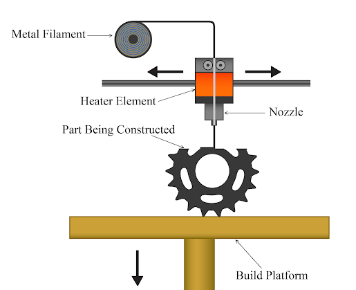
A moveable (x-y movement) nozzle on a
substrate deposits a thread of molten polymeric material in the Fused
Deposition Modeling (FDM) process. After extrusion, the construction material
is heated slightly beyond its melting point (about 0.5 C) so that it hardens in
a very short period (roughly 0.1 s) and cold-welds to the preceding layer. A
stable nozzle and material extrusion rate, the installation of support
structures for overhanging features, and the speed of the nozzle head, which
impacts the slice thickness, are all crucial elements to consider. FDM systems
with two nozzles, one for component material and the other for support
material, are more recent. The support material is of poor quality and can
easily break once the entire item has been placed and removed from the
substrate. Water-soluble support structure material is employed in more current
FDM technology. By establishing air spaces between two consecutive highways,
support structure can be laid with lower density than portion density.
Fused Deposition Modeling (FDM)


